
Piezo Stage Guide: How Piezoelectric Positioning Stages Work and When to Use One
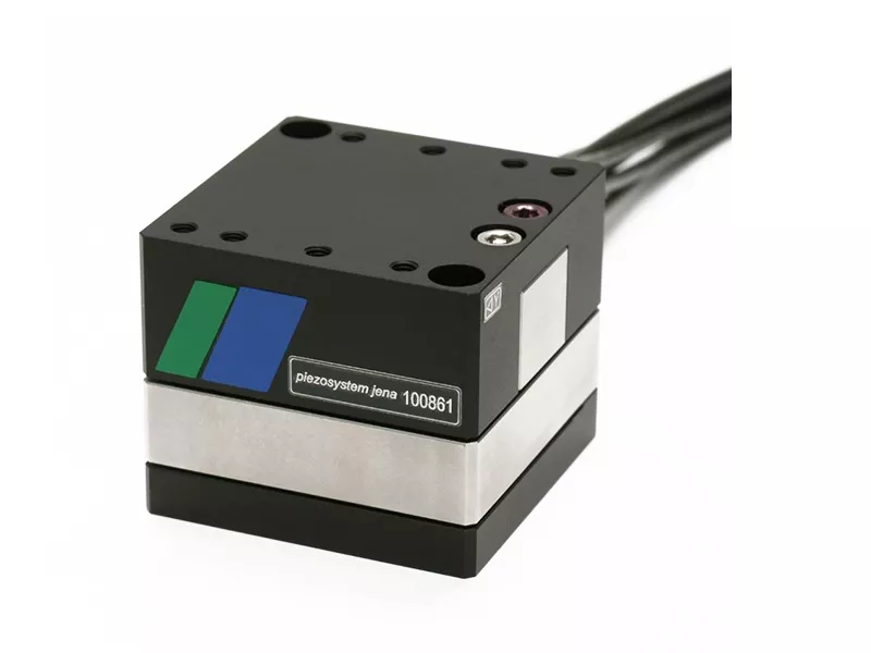
A piezo stage uses a piezoelectric actuator to produce nanometer-scale motion. This guide explains how piezo stages work, how they compare with servo stages, and where they are used in microscopy, wafer inspection and fiber alignment. Piezo stages are also called piezo nanopositioning stages.
What is a piezo stage?
A piezo stage is a precision positioning device driven by a piezoelectric actuator. When a voltage is applied, the actuator expands or contracts and moves the stage without a conventional screw or gear transmission.
Piezo stages are commonly used for nanometer-scale positioning, fast scanning and fine adjustment over short travel ranges, typically tens to several hundred micrometers. How a given stage performs depends on its mechanical design, the drive electronics and whether position feedback is used.
How a piezo stage works
The actuator is made of piezoceramic material that changes length with the applied voltage. Most piezo stages guide this motion with a flexure, a solid hinge that bends elastically and has no sliding contact surfaces.
- Flexure-guided piezo stages offer backlash-free motion without conventional sliding friction. Their positioning resolution is limited mainly by the drive electronics, sensor noise and mechanical design.
- Piezo stages can provide fast response suitable for scanning and dynamic positioning, with some models responding in the millisecond range. Actual response time depends on the stage, load and controller configuration.
Take the piezosystem jena MIPOS 600 SG objective positioner we distribute. In open loop it offers 600 µm of travel and 0.9 nm resolution. In SG closed-loop mode, travel is 500 µm and resolution is 12 nm. The manufacturer notes that these resolution figures are limited by the noise of the power amplifier and the metrology.
Resolution describes the smallest motion the system can detect or control. It should not be confused with positioning accuracy or repeatability, which depend on the stage, the feedback system and the operating conditions.
Piezoceramics also show hysteresis and creep. Open-loop control uses no position feedback, so it is affected by both. Closed-loop control uses a position sensor for feedback, which reduces positioning error and improves position stability. Resolution, travel and dynamic performance in each mode depend on the product design; the MIPOS 600 SG figures above differ between open and closed loop.
Piezo stages vs servo stages
Motor-driven stages, servo or stepper, move through a screw, a belt or a linear motor and can travel from millimeters to meters. With high-resolution encoders, some of them reach nanometer-level resolution. Piezo stages cover a much shorter range, and they are chosen for fine positioning, fast response and backlash-free motion within that range.
| Item | Motor-driven stage (servo / stepper) | Piezo stage |
|---|---|---|
| Drive | Motor with screw, belt or linear motor | Piezoceramic actuator, usually flexure-guided |
| Typical travel | Millimeters to meters | Micrometers to millimeters |
| Resolution | Depends on encoder and drivetrain, from micrometers down to nanometers | Nanometer to sub-nanometer (open loop) |
| Dynamics | Depends on the motor, moving mass and control system | Fast response, affected by load, resonant frequency and control system |
| Main limits and error sources | Vary with the drive type: mechanical play, friction, feedback error and thermal deformation | Hysteresis, creep (reduced in closed loop), electronics noise and mechanical deformation |
| Typical role | Long moves and coarse positioning | Fine positioning and scanning over short travel |
Many systems combine the two. In semiconductor inspection tools and autofocus microscopes, a motor-driven stage handles coarse positioning and a piezo stage provides the final fine adjustment.
Applications suited to piezo stages
- Microscope focusing: objective positioners such as MIPOS mount between the nosepiece and the objective and move the objective along Z for autofocus and Z-stacks. See piezo objective positioning in autofocus systems.
- Wafer inspection and metrology: these systems may require highly repeatable positioning, and piezo stages provide fine motion control where the allowable positioning error is particularly small. See piezo solutions for wafer positioning.
- Fiber alignment: fine X, Y and Z adjustment is used to find and hold the coupling peak. The acceptable offset depends on the fiber type and the coupling optics.
- Optical beam control: tilt mirror platforms such as the PSH series steer laser beams. Their travel and resolution are given in angular units; the PSH 25, for example, has an open-loop resolution of 0.2 µrad.
Translation stages specify travel and resolution in nm or µm, while tilt platforms use µrad or mrad. For long-travel material handling and pick-and-place, a motor-driven stage is usually the first option to evaluate.
piezosystem jena product series by function
| Function | piezosystem jena series |
|---|---|
| Single-axis translation | PX, PZ, PU series |
| High-dynamic positioning | nanoX, nanoSX, nanoSXY series |
| Two-axis (XY) translation | PXY series |
| Three-axis (XYZ) translation | TRITOR series |
| Five-axis positioning | PENTOR |
| Microscope objective positioning | MIPOS, nanoMIPOS series |
| Tilt mirrors (angular adjustment) | PSH, PKS series |
How to choose a piezo stage
Start with the travel, the resolution or repeatability you need, the number of axes, the load, the dynamics and whether closed-loop control is required. A complete system requires compatible drive electronics, and closed-loop models also require position feedback and control. Include these when estimating the total system cost.
If you would like help with a selection, you are welcome to send your requirements through our enquiry form. Drawings or the model numbers you currently use help us reply with specific options sooner. For a first comparison on your own, the AI selection assistant can narrow down candidate models. The full range is in the piezosystem jena product list.
Nahshon is the exclusive distributor of piezosystem jena in Taiwan and also supplies customers in Southeast Asia.
Travel, load, resolution, environment — share whatever you have
Send SpecsChat on LINEOr call 02-2765-8812FAQ
My accuracy requirement is around 1 µm. Do I need a piezo stage?
Not necessarily. For positioning accuracy around 1 µm, a servo or stepper stage may be enough. If you also need fast fine adjustment, nanometer-scale scanning, low hysteresis or long-term position holding, evaluate the full set of conditions. A piezo stage and a servo stage solve different problems, so the choice should follow the application.
How much travel can a piezo stage provide?
Mainstream products cover tens to hundreds of micrometers. The MIPOS 600 SG offers 600 µm in open loop with 0.9 nm resolution, and 500 µm with 12 nm resolution in closed loop. For longer distances, a motor-driven stage handles coarse positioning and the piezo stage is mounted on top for the final adjustment.
Can I use the stage without other components?
A complete piezo positioning system requires compatible drive electronics. Closed-loop models also require position feedback and control. These components should be included when estimating the total system cost.
What does a piezo stage cost?
It depends on the number of axes, the travel and whether you need open-loop or closed-loop control, so the range is wide. Send us the travel, number of axes and control requirements, and we can prepare a quotation.
Can I test a stage before buying?
Demo and loan arrangements can be discussed. The available models and timing need to be confirmed with us in advance.
What applications does piezosystem jena cover?
piezosystem jena develops piezoelectric positioning systems for precision motion, microscopy, optical alignment and other applications. Custom configurations can be discussed based on specific requirements. In Taiwan, Nahshon is the exclusive distributor.
For nanometer-level positioning, should I look at a piezo stage or another nanopositioning stage?
This guide covers how piezo stages work and where they fit. Nanopositioning can also be done with linear-motor stages and high-resolution encoders, which offer longer travel. Compare the required travel, resolution and dynamics, then choose the drive type. Our team can help with the comparison based on your application.